Week 1

To begin with the robosumo module we first learned about the schedule for the next twelve weeks, each week with another part of the project that would have to be completed for both the tip the can competition on week 5 and the final robosumo competition on week 10. After being split up into our groups, each group was given a number that we had to change into binary code which after building our first LED circuit, we would pass this binary code through the circuit in order to display a pattern with the LEDs.

The first circuit with a single LED

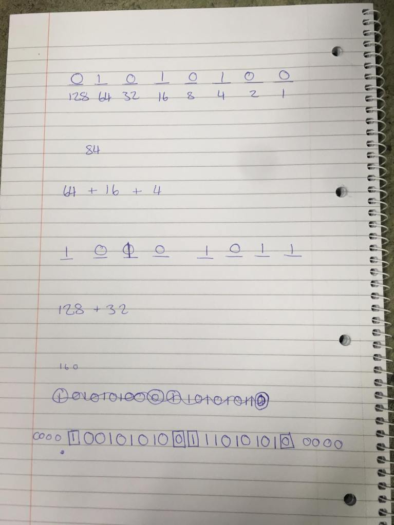
As can be seen in the above video we built this curcuit and used the arduino coding software in order to make the LED flash on for 1 second and off for 1 second and to loop over again. after completing this simple circuit we then changed our group number 84 to the binary code 10101011. The (FIG1) shows the calculations to change from 84 to binary code.
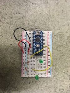
Our color coding for our wires that we would use throughout this project was red for positive, black to the negative, yellow to the signal and purple to the motors. Next we built a circuit with 2 LEDs that would allow us to show a pattern made by the new binarry code. Every 1 symbolising for LED1 to be on while LED2 is off and viceversa for every 0. The circuit needed for part 2 can be seen in (FIG2).
Now using the binary code we had to make the LEDs show our pattern in order to pass the pattern test for week 1. Using the following coding (FIG3) we succesfully completed our first test in the robosumo module.

void setup()
{
  // Digital output for LED on pin D2
  pinMode(2, OUTPUT);
  pinMode(3, OUTPUT);

  int Space;
}

void loop()
{

  int Space = 500;
  
  digitalWrite(2, HIGH);
  digitalWrite(3, LOW);
  delay(5*Space);            //0 for 5 Seconds to Start


  digitalWrite(2, LOW);
  digitalWrite(3, HIGH);    
  delay(Space);             //Start Bit


  digitalWrite(2, HIGH);
  digitalWrite(3, LOW);
  delay(2*Space);          // 0 0 

  digitalWrite(2, LOW);
  digitalWrite(3, HIGH);
  delay(Space);             //1

  digitalWrite(2, HIGH);
  digitalWrite(3, LOW);
  delay(Space);             //0

  digitalWrite(2, LOW);
  digitalWrite(3, HIGH);
  delay(Space);             //1

  digitalWrite(2, HIGH);
  digitalWrite(3, LOW);
  delay(Space);             //0
  
  digitalWrite(2, LOW);
  digitalWrite(3, HIGH);
  delay(Space);             //1

  digitalWrite(2, HIGH);
  digitalWrite(3, LOW);
  delay(Space);             //0


  digitalWrite(2, HIGH);
  digitalWrite(3, LOW);     
  delay(Space);             //End Bit


  digitalWrite(2, LOW);
  digitalWrite(3, HIGH);      
  delay(Space);             //Start Bit


  digitalWrite(2, LOW);
  digitalWrite(3, HIGH);      
  delay(Space);             //1

  digitalWrite(2, LOW);
  digitalWrite(3, HIGH);
  delay(Space);             //1

  digitalWrite(2, HIGH);
  digitalWrite(3, LOW);
  delay(Space);             //0

  digitalWrite(2, LOW);
  digitalWrite(3, HIGH);
  delay(Space);             // 1

  digitalWrite(2, HIGH);
  digitalWrite(3, LOW);
  delay(Space);             // 0

  digitalWrite(2, LOW);
  digitalWrite(3, HIGH);
  delay(Space);             // 1

  digitalWrite(2, HIGH);
  digitalWrite(3, LOW);
  delay(Space);             // 0

  digitalWrite(2, LOW);
  digitalWrite(3, HIGH);
  delay(Space);             // 1

  digitalWrite(2, HIGH);
  digitalWrite(3, LOW);
  delay(Space);             // End Bit


  digitalWrite(2, HIGH);
  digitalWrite(3, LOW);
  delay(5*Space);           // 0 for 5 Seconds to End
  
  
}

After passing the code through the circuit we succesfully completed the light pattern test as can be seen in the following video and thus completed week one of the module.
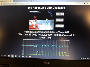
Completed pattern light test

Week 2

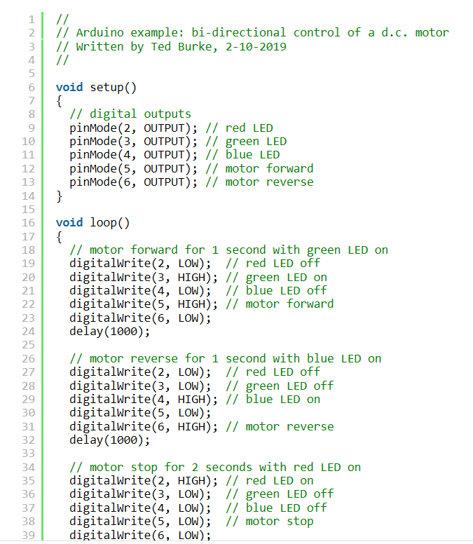
Week two began with building the first part of the circuit that will be connected to the battery pack and the motors. The battery pack must be connected in order for the motors to work at a significant rate. The following coding (FIG5) was first applied to the Arduino apparatus that would allow for the robot to move forward for 2 seconds, move backwards for 1 second, then stop for 5 seconds and then looping over. This allowed for the robot to be able to move bi-directionally.

FIG5 Bi-Directional coding example

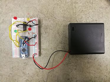
Next the two motors needed wires soldered to them in order to be connected to the circuit. once the wires are soldered to the motors they are then taped back over the motors to make it easier for completing the robot in the long run. In FIG6 you can see how the battery pack and the motors are connected to the breadboard.

FIG6 Battery pack and breadboard

Next we uploaded the coding from FIG5 to the Arduino and the circuit in order to complete our bi-directional feature of the robot. With this completed it meant we had our motors working and a huge step towards the completed tip the can robot for week 5.

Week 3

Week three saw us starting with a new arduino due to the fact that the previous arduino suffered technical difficulties and was unable to execute the coding the way we expected but once a new arduino was acquired the code for bi directional was applied by cillian and our motors were completed. Next we moved onto adding the switch to our circuit. This switch would be used as an indicator for the robot to know when it has tipped the can and reverse backwards away from the can once it has done so.

As seen in the image above, a red wire was soldered to the open leg of the switch and another yellow wire to the common leg of the switch (colour coding of wires to be found in week 1). We then tested the switch with the motors connected as can be seen in the video below.

As you can see the switch worked as intended with the motors allowing us to move on with the rangefinder finalising our preparations for week 5’s tip the can competition. As i wasn’t available this week you can find a more in depth version of the accounts of this week on my fellow colleagues pages @ https://cillianrobosumo.wordpress.com/2020/02/21/week-4-rangefinder-and-final-preparations-for-tip-the-can/ or @ https://ericsrobosumophotography.photo.blog/blog-feed/.

Week 4

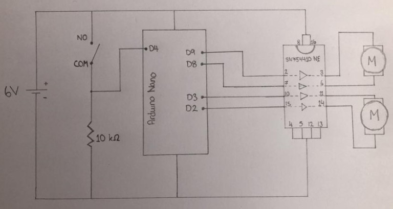
This week began with connecting the HC-SR04 ultrasonic rangefinder to the circuit. This was the piece of apparatus that would be used to tell the robot where the can was and guiding it towards the can by sending out ultrasonic waves that would rebound back off the can to a receiver giving the robot the knowledge of where to drive towards. This allowed the distance to be calculated between the can and the robot.

In the video above you can see how the rangefinder tells the motors to move forward once an object or surface within the given radius is found.

This following code was applied to the arduino to give the instructions of what to do when the rangefinder picked up the position of the can. We also had a switch within our coding so that once the robot did hit the can it would then reverse so to abide by the competition rules.

// Code used for Tip the Can for RoboSumo
// Written by Cillian O'Brien
// Last Updated 26.02.2020

  // Defining Pins rather than using ints, seems to solve a few issues that were happening 
  #define button 4      // Switch button
  #define echoPin 5     // Trigger Pin for Sensor
  #define trigPin 6     // Echo Pin for Sensor

  long duration, distance;      // Defines variables for duration of pulse, and distance from object
  
void setup() {
  Serial.begin(9600);   // Sets baud rate for info from sensor [FOR TESTING]
  pinMode(trigPin, OUTPUT);   // Set up the trigger pin
  pinMode(echoPin, INPUT);    // Set up the echo pin
  
  pinMode(2, OUTPUT); // Motor 1 Forward
  pinMode(3, OUTPUT); // Motor 1 Backward
  pinMode(8, OUTPUT); // Motor 2 Forward
  pinMode(9, OUTPUT); // Motor 2 Backward

  pinMode(button, INPUT);  // Switch Voltage Check
  
}

void loop() {
  
  int push = digitalRead(button);      // Setting up var for reading when button is pushed

  digitalWrite(trigPin, LOW);
  delayMicroseconds(20);
  digitalWrite(trigPin, HIGH);  // Set trigPin high
  delayMicroseconds(20);        
  digitalWrite(trigPin, LOW);   // Send pulse for 20 us
  

  duration = pulseIn(echoPin, HIGH);  //pulseIn detects the duration of pulses from trigger
  distance = (duration/2)*0.034;  // Time to reach object * Speed of Sound in cm/us
  

  Serial.print(distance);   // This is to print the distance (in cm) of the rangefinder
  Serial.println(" cm");    // is detecting [FOR TESTING]
  

  if (push == 1) {          // Button is Pressed [Hit the Can]

    digitalWrite(2, LOW);         // Keeps Going Forward for 1 Second
    digitalWrite(3, HIGH);        
    digitalWrite(8, LOW);
    digitalWrite(9, HIGH);
    delay(1000);
    
    digitalWrite(2, HIGH);        // Goes Backward for 2 Seconds
    digitalWrite(3, LOW);         
    digitalWrite(8, HIGH);        
    digitalWrite(9, LOW);
    delay(2000);

    digitalWrite(2, LOW);         // Stops for 60 Seconds
    digitalWrite(3, LOW);
    digitalWrite(8, LOW);
    digitalWrite(9, LOW);
    delay(60000);
    
  }
  
  else {                    // Button is Not Pressed [Hasn't Hit the Can]

    if (distance < 10) {
      // Object within Range
      digitalWrite(2, LOW);      // Goes Forward [Sees Can]
      digitalWrite(3, HIGH);
      digitalWrite(8, LOW);
      digitalWrite(9, HIGH);
    }
    else {
      // Object Out of Range
      digitalWrite(2, LOW);       // Turns [Default Mode]
      digitalWrite(3, HIGH);
      digitalWrite(8, HIGH);
      digitalWrite(9, LOW);
    }
  }

  delay(50); // Delay to allow ultrasonic reflections to die out
  

}

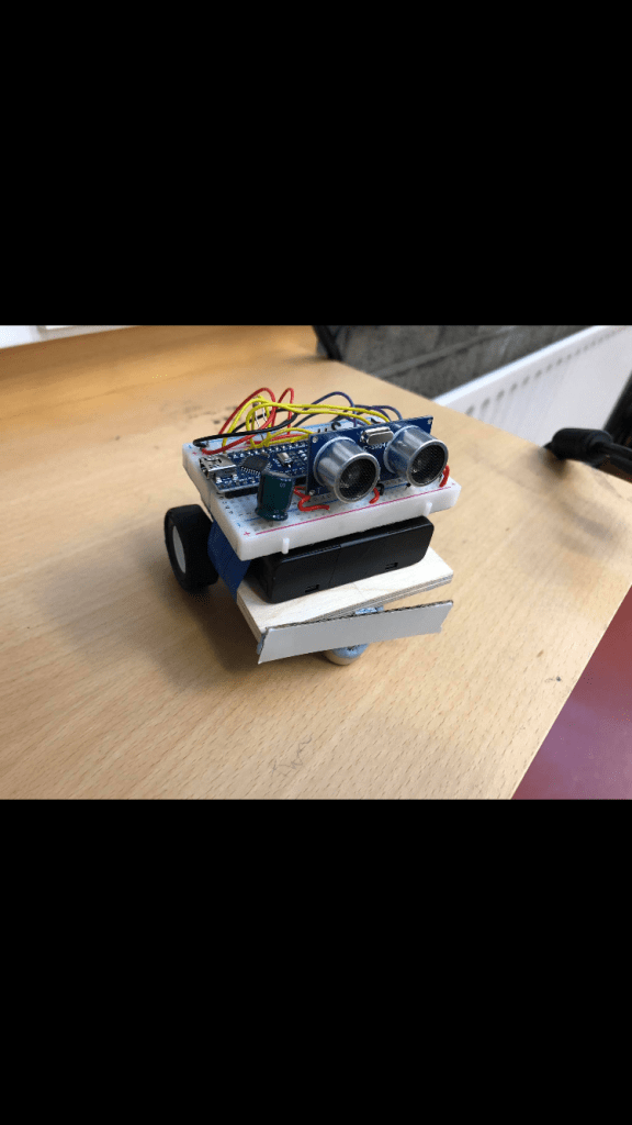
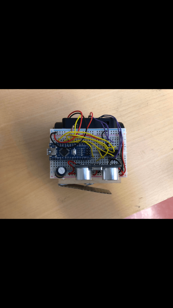
After successfully building the circuit with the working motors, sensor, switch and the correct coding uploaded to the arduino that is needed for the Tip The Can (TTC) competition in the previous weeks we were now able to research how we would piece the main components together in order for them to successfully complete the TTC. At the time we were not aware of the laser cutting service available to build the shell so instead we went for a small piece of plywood that was used as a platform to rest the battery pack and breadboard on whilst the switch and motors were connected on the bottom. Using blue-tac and glue we were able to secure each part together of the robot to finish with our final design below.

Thus we were ready for week 5’s competition……

Week 5

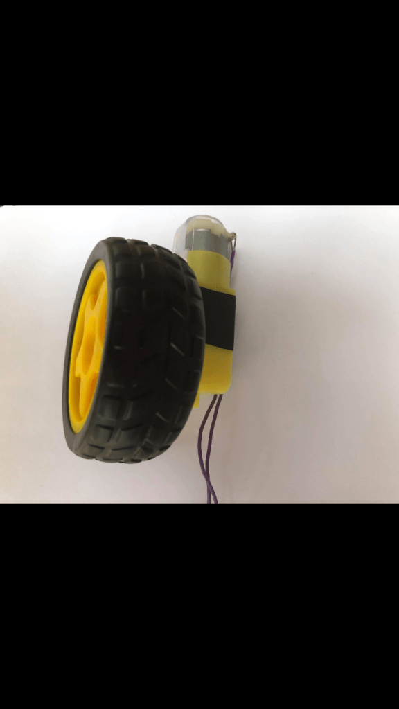
TIP THE CAN (TTC) WEEK 1. The class began with a last minute race to try and find a new pair of wheels that would fit the motors. The wheels in the end that we did use are pictured below and provided us the opportunity to take our first few attempts at the tip the can competition.

The following code was used for the TTC competition giving the instructions to rotate on its own axis, pick up a reading for the can, move towards the can and finally once the switch had been pressed to reverse and stop.

// Defining Pins rather than using ints, seems to solve a few issues that were happening 
  #define button 4      // Switch button
  #define echoPin 5     // Trigger Pin for Sensor
  #define trigPin 6     // Echo Pin for Sensor

  long duration, distance;      // Defines variables for duration of pulse, and distance from object
  
void setup() {
  pinMode(trigPin, OUTPUT);   // Set up the trigger pin
  pinMode(echoPin, INPUT);    // Set up the echo pin
  
  pinMode(2, OUTPUT); // Motor 1 Forward
  pinMode(3, OUTPUT); // Motor 1 Backward
  pinMode(8, OUTPUT); // Motor 2 Forward
  pinMode(9, OUTPUT); // Motor 2 Backward

  pinMode(button, INPUT);  // Switch Voltage Check
  
}

void loop() {
  
  int push = digitalRead(button);      // Setting up var for reading when button is pushed

  digitalWrite(trigPin, LOW);
  delayMicroseconds(20);
  digitalWrite(trigPin, HIGH);  // Set trigPin high
  delayMicroseconds(20);        
  digitalWrite(trigPin, LOW);   // Send pulse for 20 us
  

  duration = pulseIn(echoPin, HIGH);  //pulseIn detects the duration of pulses from trigger
  distance = (duration/2)*0.034;  // Time to reach object * Speed of Sound in cm/us
  

  if (push == 1) {          // Button is Pressed [Hit the Can]

    digitalWrite(2, LOW);         // Keeps Going Forward for 1 Second
    digitalWrite(3, HIGH);        
    digitalWrite(8, LOW);
    digitalWrite(9, HIGH);
    delay(1000);
    
    digitalWrite(2, HIGH);        // Goes Backward for 2 Seconds
    digitalWrite(3, LOW);         
    digitalWrite(8, HIGH);        
    digitalWrite(9, LOW);
    delay(2000);

    digitalWrite(2, LOW);         // Stops for 60 Seconds
    digitalWrite(3, LOW);
    digitalWrite(8, LOW);
    digitalWrite(9, LOW);
    delay(60000);
    
  }
  
  else {                    // Button is Not Pressed [Hasn't Hit the Can]

    if (distance < 80) {
      // Object within Range
      digitalWrite(2, LOW);      // Goes Forward [Sees Can]
      digitalWrite(3, HIGH);
      digitalWrite(8, LOW);
      digitalWrite(9, HIGH);
    }
    else {
      // Object Out of Range
      digitalWrite(2, LOW);       // Turns [Default Mode]
      digitalWrite(3, HIGH);
      digitalWrite(8, HIGH);
      digitalWrite(9, LOW);
    }
  }

  delay(50); // Delay to allow ultrasonic reflections to die out
  

}

Our lecturers provided us with a mock up round platform to emulate the actual competition platform. This gave us an insight into how well our robot worked at this point. Straight away we noticed a grip problem due to the weakness of the motors and the lack of friction on the surface. We decided to use a small rubber piece strapped around the wheels to give it a better hold on the surface and to compromise for the lack of force being applied from the motors. This meant that our test runs were successful from then on and allowed us to make an attempt at a recorded time. Our first try was not a success story due to the fact that when our robot did hit the can it didn’t press the switch in to a point that enabled it to send the message to reverse away. The result was changing what side the switch would slope out from to allow for minimal pressure to be applied on the switch for it to work.

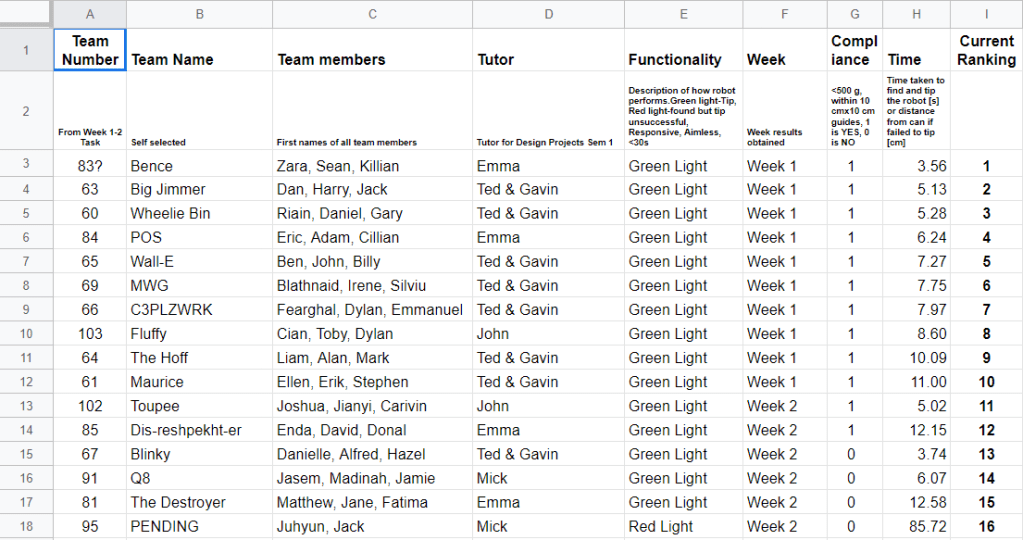
Our second attempt ended up being the time and run we used giving us a great time of 6.24 seconds as can be seen on the screenshot below of the live score sheet for the competition that would run over week 5 and 6. It can be found at this link also (https://docs.google.com/spreadsheets/d/1Tojza0bPpKwD6aS6lRoePU9EUXQcxCEIINZDWM7AKm4/edit#gid=0)

Overall we placed in 4th place with our timing and the fact that we completed our test in week 5/ TTC week 1 meant we would finish above anyone who completed it the following week regardless of there times.

Unfortunately due to unforeseen circumstances the footage of our competition was lost and could not be remade.

(This would have been a benefit for the actual competition however due to the fact it would not be going ahead due to covid 19 this would be the only competition we would be judged on.)

Week 6

Due to the fact that we had completed our TTC in the first week of the competition this gave us an upper hand to allowing us to begin our design and build for the actual robosumo competition (N/A). Our idea initial was to change the motors and try and find some better more efficient ones online that would give us that extra push against the other competitors. We also knew we had to stay within the competition rules of a 10 x 10 x 10 cm sizing and below the weight of 500g. This meant using a lightweight material for the chassis and made it harder to use some of the ideas we had originally planned.

We also had a light sensor (pictured above) that we were not even sure about even using within our design due to the fact that our plan was for the robot to spin on its own axis and once the rangefinder picked up an opponent it would drive towards it. We felt this was more beneficial because other robots would spend time bouncing around the platform before it cam into contact with us whereas our robot would cut out that nonsense and move towards engaging in the fight straight away. The plan was to think about it and come back next week with a final decision.

After I took measurements for the pieces we knew we would use, sketches were drawn up of these pieces.

Our plans were to go away this week and come up with an idea of what we wanted our final design to look like and to conjugate again in week 7.

Week 7

As is known by now but not at the time this would be our final week of college and thus our final week of design engineering robosumo module.

The aim of this week was to start settling on a final design for the competition. I had experience with solid works and got to work on rendering models of parts that would be used towards the final design (unfortunately this work cannot be sampled as it is on a file in college). We also confirmed that we would not be incorporating the light sensor into our design due to the fact that it didn’t fit our plan for the competition.

The first draft of the competition coding was completed as can be found below that would help to tweak and trouble shoot any problems with the motors and sensor.

// Code used for RoboSumo Tournament
// Written by Cillian O'Brien
// Last Updated 11.03.2020

  #define button 4      // Switch button
  #define echoPin 5     // Trigger Pin for Sensor
  #define trigPin 6     // Echo Pin for Sensor

  long duration, distance;      // Defines variables for duration of pulse, and distance from object

void setup() {
  Serial.begin(9600);   // Sets baud rate for info from sensor [FOR TESTING]
  
  pinMode(trigPin, OUTPUT);   // Set up the trigger pin
  pinMode(echoPin, INPUT);    // Set up the echo pin
  
  pinMode(2, OUTPUT);         // Motor 1 Forward
  pinMode(3, OUTPUT);         // Motor 1 Backward
  pinMode(8, OUTPUT);         // Motor 2 Forward
  pinMode(9, OUTPUT);         // Motor 2 Backward

  pinMode(button, INPUT);     // Switch Voltage Check
}

void loop() {
  int push = digitalRead(button);      // Setting up var for reading when button is pushed

  digitalWrite(trigPin, LOW);
  delayMicroseconds(20);
  digitalWrite(trigPin, HIGH);  // Set trigPin high
  delayMicroseconds(20);        
  digitalWrite(trigPin, LOW);   // Send pulse for 20 us
  

  duration = pulseIn(echoPin, HIGH);  //pulseIn detects the duration of pulses from trigger
  distance = (duration/2)*0.034;  // Time to reach object * Speed of Sound in cm/us
  

  Serial.print(distance);   // This is to print the distance (in cm) of the rangefinder
  Serial.println(" cm");    // is detecting [FOR TESTING]

  if (button == 1) {
    Forward();
  }

  else if (distance < 10) {
    Forward();
  }
  
  else {
    Turn();
  }
}

void Turn(){
  digitalWrite(2, LOW);
  digitalWrite(3, HIGH);
  digitalWrite(8, HIGH);
  digitalWrite(9, LOW);
}

void Forward() {
  digitalWrite(2, LOW);
  digitalWrite(3, HIGH);
  digitalWrite(8, LOW);
  digitalWrite(9, HIGH);
}

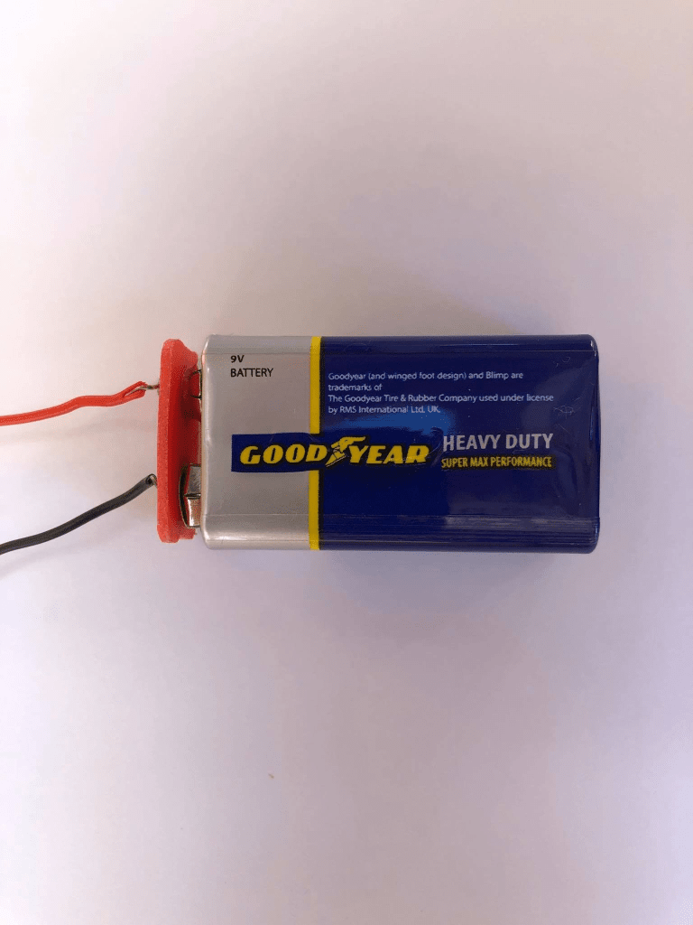
The battery pack was replaced with a 9v battery allowing us to decrease the weight of the overall robot whilst also improving the speed and ability of the motors.

I enquired about laser cutting option for the robot but due to the fact that the competition was canceled nothing was acted on and work on the final design was suspended.

Unfortunately due to covid 19 the actual robosumo competition was canceled and results would be taken from TTC only, as seen on week 5.

Design a site like this with WordPress.com
Get started